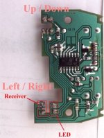
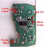
As has already been mentioned, the tracker ball uses the same system as most mice for positioning. The one
I have is a Wico, and it has two rollers mounted on bearings, that rotate two circular vanes at 90 degree
opposed positions. Each vane has a small circuit board on which is mounted two combined LED/Receiver
unit's. Each board has four wires leading to the outside world.
The wires are coloured Red, Black (common to both boards) and then Yellow and Green for one board and
Purple and Blue for the other.
Since they are designed to work with standard arcade boards, the voltage for the Red was assumed to be 5v,
the black was ground. So that just leaves 2 wires for each for the output of the optical receivers.
Joining the Two
If we look at the board I removed from inside my Mitsumi Mouse, you will see that for each direction there
is a single LED and a single Receiver
However, the receivers are mounted using 3 pins, since each contains two separate detectors.
One of these pins is the power supply and the other two the outputs.
A quick check with a multimeter (whilst holding a piece of card to prevent light activating the outputs)
soon indicated which pin was for the 5v supply. (for the unbranded mouse it was the central pin,
but the mitsumi uses the outside pin)
You should be able to verify this quite easily, follow the tracks from these pins and they should go back

Since we want to use the LED's and receivers on the tracker ball, I removed both LED's and Receivers
from the mouse controller PCB. Since the LED and receivers were not directly connected to the power
supply. But were instead connected via various resistors (which the tracker ball PCB's already have), I
proceeded to connect the 5v and ground to the relevant pins of the header plug where the serial lead
connects (again, located using a multimeter).

Each of the other wires from the receivers on the controller boards were connected to the pads that used to
contain the smaller receiver units. (it doesn't matter too much which way round - it can be corrected later).
Powering up the PC with the tracker ball plugged in revealed that this mouse worked OK both at low and
high speeds. If at this point you discover that up/down or left/right are reversed, then you need simply swap
the two wires to that receiver over. If up/down is left/right and left/right is up/down, then open up the
tracker ball assembly and swap the two circuit boards over (it's quicker than re-wiring!).
Finally
I mounted the tracker ball centrally in the control panel of my cabinet (the only place it would fit) and
connected it to the PC. If you wish to keep in the spirit of the Jamma-PC project then make the connections
via a removable header plug, then you can easily unplug the mouse board and connect the tracker ball
directly to any PCB's that require one.
For software, I used an old IBM mouse driver, rather than any of the newer ones I had, as this has no
special acceleration settings, and instead gives a nice linear response which I find matches the various
arcade games nicely. (You could use a newer driver and disable them, or you may find that you prefer
them).
So, if you have a tracker ball, or see one cheap anywhere (I don't know if Brian has any more), and don't
want to spend megabucks connecting it to your PC, start examining the cheap mice down at the local
computer shop!
If you do connect a tracker ball up in this way, then let us know what make/model mouse you used and we
can add them to this site and start a compatibility list